Electrostatic discharge (ESD) immunity testing (IEC 61000-4-2)
How ESD immunity tests work: the human-body model, contact and air discharge, indirect discharge, test levels, setup and what changed in the 2025 edition.
A person walking across a carpet can charge to thousands of volts. Touching a keyboard, a connector or a metal case then discharges that charge in a few nanoseconds, with a current spike that couples into the electronics. ESD immunity testing reproduces that event in a controlled way.
The model
The basic standard is IEC 61000-4-2 (European adoption: EN IEC 61000-4-2). The test generator represents a charged person holding a metal object: an energy-storage capacitor of about 150 pF discharges through a resistor of about 330 Ω through the tip of the generator. The standard does not fix the circuit values; what matters is the shape of the discharge current (a very fast first peak of nanosecond rise time followed by a slower tail), which is specified and verified by calibration with a current target and a wide-bandwidth oscilloscope.
Discharge methods
- Contact discharge: the tip of the generator touches the conductive part of the EUT before the discharge is triggered. This is the preferred method because it is more repeatable.
- Air discharge: a rounded tip approaches the EUT until the spark jumps; used on surfaces and apertures where contact discharge cannot be applied (for example insulated surfaces and gaps).
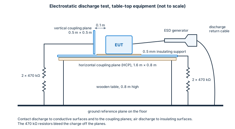
- Indirect discharge: the discharge is applied to a horizontal coupling plane (HCP) under the EUT and a vertical coupling plane (VCP) beside it, to simulate discharges to nearby objects.
Test levels
The standard defines severity levels for each method. For contact discharge the levels are 2, 4, 6 and 8 kV; for air discharge 2, 4, 8 and 15 kV, with higher or “special” levels allowed by agreement. Product standards choose the level, commonly 4 kV contact and 8 kV air for general equipment. Equal voltages do not mean equal severity across methods; the methods differ.
Setup
The EUT sits on a non-conductive table (typically 0.8 m high) on a reference ground plane that is connected to protective earth, with coupling planes as needed. Cables are laid out as in normal use and insulated from the coupling plane. The discharge return cable from the generator to the ground plane has a prescribed length and layout; the same layout that was used in calibration is used in testing. Floor-standing equipment sits on an insulating support above the ground plane.
Equipment that is not earthed (battery-powered, double-insulated) can accumulate charge; the charge has to be bled off between discharges, with a bleeder cable of specified resistance, so that pulses do not add up.
Procedure
- Choose test points that are accessible to people during normal use (connectors, buttons, enclosure seams, displays) and ones that the standard requires (coupling planes).
- Apply a minimum number of single discharges at each point per polarity, at a repetition rate of at least one second between pulses, with the EUT monitored for correct operation.
- Air discharge is applied through the levels in steps up to the specified level; contact discharge is applied at the specified level.
- Humidity and temperature are controlled because they affect the discharge, especially air discharge.
Typical findings
- resets and lock-ups of microcontrollers through the ground or reset network;
- latent damage to I/O devices without protection;
- corrupted displays or touch controllers;
- failure at connector shells and seams due to poor grounding of the case.
Remedies include a robust protective-ground path and a low-impedance connection from connector shells to the chassis, transient-voltage suppressors at inputs, good separation of sensitive circuits, spark gaps or creepage paths, and software that handles transient errors.
What changed in the 2025 edition
The third edition of IEC 61000-4-2 was published in 2025 and adopted by CENELEC as EN IEC 61000-4-2:2025, replacing the 2008/2009 edition. Changes include a calibration requirement for the air-discharge tip, an improved current-calibration procedure, new normative setups for wall-mounted and wearable equipment, a stronger treatment of measurement uncertainty, and the move of post-installation testing guidance to an informative annex. Check the transition dates that apply in your market before relying on either edition.
Related methods
ESD for automotive components is tested to ISO 10605, which uses different capacitor and resistor values and different setups. Handling-level device ESD sensitivity (for example “human-body model” classifications for integrated circuits) is a separate topic covered by other standards and is not what IEC 61000-4-2 tests.