Filtering for EMC: topologies, insertion loss, placement and limits
How EMC filters work: differential and common mode, X and Y capacitors, chokes, filter topologies, insertion loss and why impedance, placement and parasitics decide performance.
An EMC filter lets wanted signals pass and attenuates unwanted ones. A power-line filter is a low-pass network: it passes the 50/60 Hz (or DC) power and attenuates radio-frequency noise. Filters are used at cable entries to reduce conducted emission, to protect against conducted disturbance, and to keep noise out of or inside shielded enclosures.
Differential mode and common mode
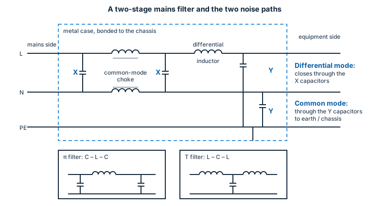
Noise on a line pair has two components (coupling paths), and a filter normally has an element for each:
- Differential mode (DM): between the conductors. Filtered by series inductance and X capacitors (across the lines).
- Common mode (CM): the same on all conductors, relative to ground. Filtered by a common-mode choke (two or more windings on one core, which presents high impedance to CM current and almost none to DM current) and Y capacitors (line to ground/earth).
Because Y capacitors carry current to earth at the mains frequency, their value is limited by touch-current (leakage current) limits in the safety standards. That is an EMC–safety trade-off: more CM filtering by capacitance is limited by safety, so the choke does most of the work.
Topologies
- A single capacitor or inductor (one element).
- L-section (an inductor and a capacitor).
- π (pi) filter: capacitor – inductor – capacitor; the capacitors face the source and the load.
- T filter: inductor – capacitor – inductor.
More stages give a steeper roll-off and higher attenuation at the cost of size, weight and cost. As a rule, the filter works best when the element facing a low-impedance side is a capacitor (shunt) and the element facing a high-impedance side is an inductor (series), because the filter then adds mismatch to the noise path.
Insertion loss
Insertion loss is how much more the noise is attenuated with the filter than without it, in dB at each frequency: 20 dB is a voltage reduction of 10 times, 40 dB is 100 times, 60 dB is 1,000 times.
Insertion loss depends on the source and load impedances. Catalogue figures are measured in a specified system, commonly 50 Ω source and 50 Ω load, so they are a comparative benchmark rather than the loss in a real product, where the mains impedance varies with frequency and location. CISPR 17 describes methods that use worst-case impedance combinations (for example, a low source and high load) to bracket the real behaviour.
Parasitics limit the bandwidth
Real components are not ideal:
- an inductor has parasitic capacitance and becomes capacitive above its self-resonant frequency;
- a capacitor has parasitic inductance (ESL) and becomes inductive above its self-resonance;
- coupling between the input and the output side of a filter bypasses it at high frequency.
Good construction (short leads, low-inductance capacitors, a metal case that separates input and output, feed-through capacitors) is what extends the useful range to high frequencies.
Placement and mounting
- Put the filter where the cable enters, at the shield or enclosure boundary; the filter’s case or ground bonded to the chassis with a short, wide, low-inductance connection.
- Keep filtered and unfiltered wires separate; running them together lets noise jump past the filter.
- For shielded rooms and enclosures use filters that mount through the shield wall with 360° bonding, so that the shield is not broken.
- Check that the choke does not saturate at the maximum DC or AC current.
Other suppression components
- Ferrite cores and beads: add lossy impedance to a conductor over a wide band, useful for cable common-mode currents.
- Varistors, TVS diodes and gas-discharge tubes: protect against transients (see EFT/burst and surge).
- Feed-through capacitors: capacitors built into the wall of an enclosure so that the signal passes straight through.
Common mistakes
- a filter that is grounded through a long wire;
- an unfiltered cable beside the filtered one;
- a filter chosen from catalogue insertion loss only, without checking the impedance conditions;
- a choke that saturates under load or surge;
- exceeding leakage current limits with too much Y capacitance.