Surge immunity testing (IEC 61000-4-5)
What surges are, how the combination-wave surge test is applied to power and communication lines, waveforms, source impedance and typical protection.
A surge is a slow, high-energy transient on the supply or communication lines. Typical causes are lightning striking near the lines and switching of power systems (capacitor banks, large loads, fault clearing). Surges are far slower and carry far more energy than EFT bursts, and they can destroy components rather than only upset them.
The waveform (IEC 61000-4-5)
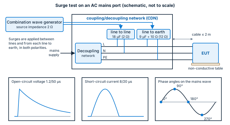
The basic standard is IEC 61000-4-5 (European adoption: EN 61000-4-5). The main waveform comes from a combination wave generator, which delivers:
- an open-circuit voltage wave with a 1.2/50 µs shape (front time 1.2 µs, time to half value 50 µs);
- a short-circuit current wave with an 8/20 µs shape.
The same generator therefore behaves as a voltage source into a high impedance and a current source into a low one. For communication lines with long outdoor runs, the standard provides a 10/700 µs generator with a different source impedance; the combination wave is also used for many signal lines.
Source impedance and coupling
- For line-to-line coupling on AC mains, the generator’s effective source impedance is 2 Ω; for line-to-ground coupling an additional series resistance brings it to 12 Ω. These values, not just the voltage, define the energy delivered.
- Surges are injected through a coupling/decoupling network that applies them to the EUT while protecting the supply and any auxiliary equipment.
- The surge is applied at defined phase angles of the mains voltage (for example 0°, 90°, 180° and 270°) because the phase affects how protection devices and power stages react.
Test levels and procedure
Levels commonly run from 0.5 kV to 4 kV (the product standard chooses; line-to-line levels are usually lower than line-to-ground). A set number of positive and negative surges (commonly five of each polarity) are applied with a repetition rate of at most one per minute, with the EUT in operation and monitored.
Typical findings
- damage to input rectifiers, varistors and filter capacitors;
- latch-up and resets of control electronics;
- failure of communication interfaces on long cables.
Protection concepts
- Coordinated protection stages: a primary stage (gas-discharge tube or large varistor) takes the bulk of the energy; a secondary stage (smaller varistor or TVS diode) limits the remaining voltage; series impedance between stages helps the stages share the energy correctly.
- Creepage and clearance and insulation ratings must withstand the let-through voltage.
- Grounding: a short, low-inductance path from the protection device to the protective earth.
Related safety standards
Surge withstand also appears in product safety and installation standards (for example overvoltage categories). The EMC test shows that the equipment keeps working in the specified conditions; it is not a substitute for lightning protection design of the installation.