Harmonic current emissions and voltage fluctuations (flicker)
What harmonics and flicker are, why equipment is limited (IEC 61000-3-2, 61000-3-3 and related standards), how they are measured and how designs comply.
Not all emissions are radio-frequency. Equipment connected to the public mains can also disturb the supply itself, at frequencies from a few hertz up to a few kilohertz. Two effects are regulated: harmonic currents and voltage fluctuations (flicker).
Harmonic currents
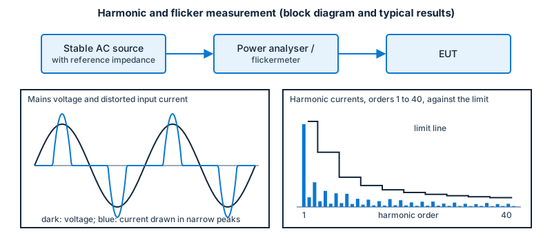
A resistive load draws a current in phase with the supply voltage and with the same sine shape. A non-linear load does not: a rectifier with a capacitor draws current only near the voltage peaks, in narrow pulses. A distorted current can be described as the sum of the fundamental (50 or 60 Hz) and harmonics at integer multiples (100/120 Hz, 150/180 Hz, and so on). The harmonics flow through the network impedance and distort the voltage for every other customer on the network, heat transformers and cables, and disturb some equipment.
Limits
IEC 61000-3-2 limits harmonic current for equipment with an input current of up to 16 A per phase. Equipment is sorted into classes (A, B, C and D) according to its type and its current waveform, and each class has its own limits for the individual harmonics (typically up to the 40th). IEC 61000-3-12 applies to equipment with a current above 16 A and up to 75 A per phase. Some equipment and some power ranges are exempt; the standards list the exclusions.
Measurement
The current harmonics are measured with a power analyser that follows IEC 61000-4-7 (a specified measurement window and grouping), with a stable AC source whose voltage and distortion are within the limits of the standard. The EUT is operated in the mode that gives the worst harmonic content.
Typical design response
- Active power-factor correction (PFC) shapes the input current to follow the voltage; it is the common solution for power supplies above a few tens of watts.
- Passive filters (inductors at the input) for lower power or lower cost.
- Careful design of dimmers, motor drives and LED drivers, which are typical problem sources.
Voltage fluctuations and flicker
Changes of the load current produce small changes in the supply voltage along the network impedance. A repetitive change can cause flicker, a visible variation in the brightness of lamps. IEC 61000-3-3 limits the voltage changes caused by equipment with an input current of up to 16 A per phase (and IEC 61000-3-11 covers equipment above 16 A up to 75 A that is subject to conditional connection).
The quantities used are:
- the short-term flicker severity Pst (assessed over 10 minutes);
- the long-term flicker severity Plt (assessed over two hours);
- the relative voltage change and its maximum.
Flicker is measured with a flickermeter specified in IEC 61000-4-15, which models the response of a lamp and the human eye, using a reference impedance that represents the supply network.
Typical sources
Equipment with large, frequent load changes: heaters controlled by on/off switching, copiers, welding equipment, motors that start often, and some compressors.
Related
The EMC product standards for multimedia equipment, household appliances and lighting list these tests together with the radio-frequency emission tests. See the EMC tests overview and the standards map.