
EMC test facilities and site validation
The main EMC test environments — open-area test sites, semi-anechoic and fully anechoic chambers, reverberation chambers, TEM/GTEM cells, shielded rooms — and how test sites are validated.
EMC measurements are only repeatable if the environment is controlled. Facilities differ in what they control: ambient radio signals, reflections, field uniformity, or the frequency range of the method.
Open-area test site (OATS)
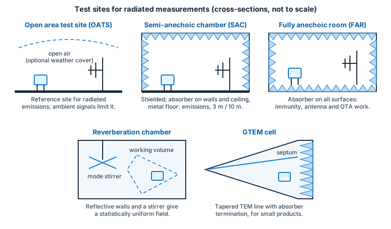
An open-area test site is the reference environment of the emission standards: a flat, open area with a conductive ground plane and no reflecting objects within a defined ellipse around the measurement axis. The antenna scans in height to find the maximum of the direct plus ground-reflected wave.
- Advantages: the reference environment; large products and long distances (3, 10, 30 m) are possible.
- Disadvantages: ambient radio and television signals, weather, and no immunity capability (the field would escape and violate radio rules).
Shielded rooms
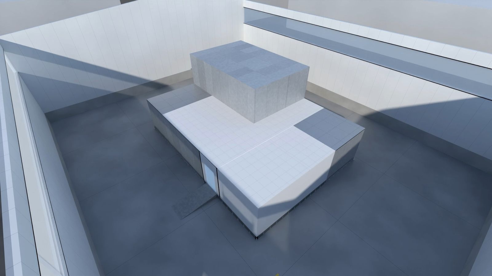
A shielded room (also called a screened room or Faraday cage) is a metal enclosure that keeps outside radio signals out and, for immunity tests, keeps the generated field in. Its quality is expressed as shielding effectiveness in dB over a frequency range. Weak points are doors, vents, cable and pipe penetrations (which need filters, waveguide-below-cutoff vents and penetration panels) and seams. Shielded rooms are used for conducted-emission tests, control rooms, amplifier rooms and for shielding other test spaces.
Semi-anechoic chamber (SAC)
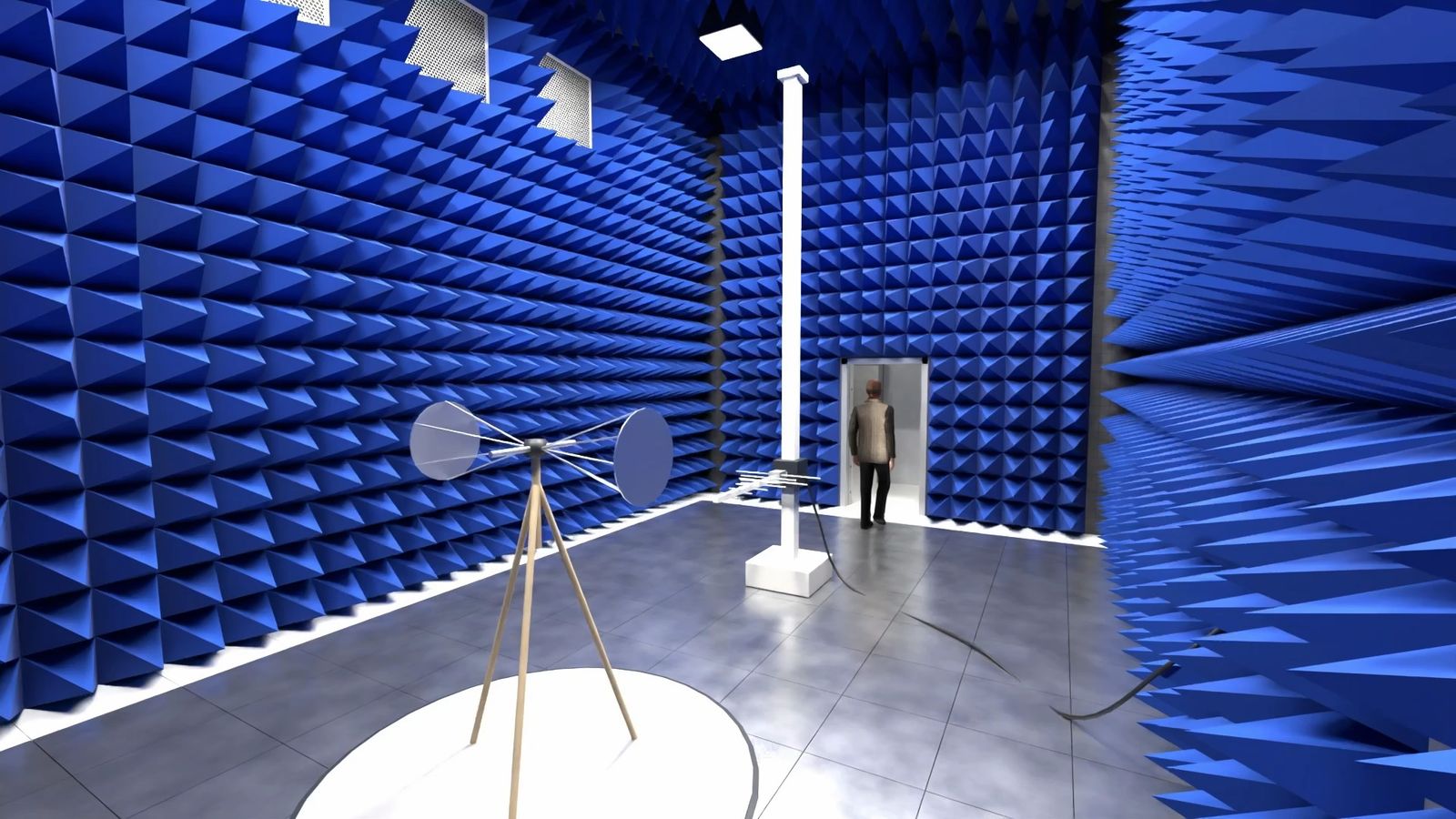
A semi-anechoic chamber is a shielded room lined with radio-frequency absorber on the walls and ceiling, but with a reflective metal floor. It recreates the OATS indoors: the floor reflection is part of the method, and the absorbers remove the reflections from the walls and ceiling.
- Typical sizes are described by the measurement distance: 3 m, 5 m or 10 m chambers (the room is larger than the distance because of the antenna height scan, the turntable and the product).
- The absorber is usually a combination of ferrite tiles (effective at the low end, about 30 MHz to 1 GHz) and pyramidal foam absorbers (effective at higher frequencies), called a hybrid lining.
- For radiated immunity in a SAC, additional absorber is placed on the floor between the antenna and the EUT so that the field in the test area is uniform.
Fully anechoic room (FAR / FAC)
A fully anechoic room has absorber on all six surfaces. It is used for radiated immunity, for emission methods above 1 GHz, for antenna and over-the-air measurements and for some other methods. The floor needs absorber (ferrite tiles and/or foam depending on the frequency range).
Reverberation chamber
A reverberation chamber is a shielded room with a large rotating metal paddle (stirrer). By moving the paddle the field is made statistically uniform and isotropic, so that the EUT is exposed to fields from all directions and polarisations. It reaches very high field strengths with relatively low amplifier power and is used for immunity and shielding measurements (IEC 61000-4-21), for automotive component immunity (ISO 11452-11) and in aerospace. Results are statistical and the method has its own calibration procedure.
TEM and GTEM cells
A TEM cell is a transmission-line structure (a flat inner conductor, the septum, between two outer plates) with a uniform field between the plates. Its upper frequency is limited by the cell size. A GTEM cell (gigahertz TEM) is a tapered, pyramid-shaped transmission line terminated with absorber, which extends the usable range to the GHz region. They are compact and are used for small products, pre-compliance and comparative measurements, with IEC 61000-4-20 describing their use for emission and immunity.
Whether a product standard accepts TEM/GTEM results for formal compliance is stated in that standard; the open-site or semi-anechoic method is normally the reference.
Automotive: absorber-lined shielded enclosure (ALSE)
Automotive component tests (CISPR 25, ISO 11452-2) use an ALSE, a shielded enclosure with absorbers on the walls and ceiling and a ground-plane bench on which the component and its harness are placed. Vehicle tests use much larger chambers with a turntable or a dynamometer (rolling road). See Automotive EMC.
How a site is validated
A test site must be shown to behave like the reference environment. The basic standards define the following checks:
| Check | What it measures | Typical frequency range |
|---|---|---|
| Normalised site attenuation (NSA) | Site attenuation between two antennas compared with the ideal ground-plane value; shows whether a SAC or OATS is good enough for emission measurements | 30 MHz–1 GHz |
| Site voltage standing-wave ratio (SVSWR) | The variation of the received signal as a source antenna is moved on a line in the test volume; shows how well the absorbers suppress reflections | 1 GHz and above, typically 1–18 GHz |
| Field uniformity (uniform field area) | The uniformity of the generated field over a grid of points, for immunity tests | 80 MHz to 6 GHz (IEC 61000-4-3) |
| Shielding effectiveness | Attenuation of the shell for magnetic, electric and plane waves | 9 kHz to 40 GHz depending on the method |
| Reflectivity of the absorber | How much power an absorber sample reflects (normal incidence) | by absorber specification |
CISPR 16-1-4 contains the NSA and site-VSWR criteria for emission sites; the acceptance limits are given in the standard (use the current edition, which has been revised in recent years). Shielding effectiveness is commonly measured to IEEE Std 299 or comparable methods.
How often? Validation is repeated at intervals set by the laboratory’s quality system, by its accreditation body, or by the standard after any change (relocation, absorber replacement, major modification). The interval is not fixed here because it differs by accreditation scheme.
Choosing a facility (for a test plan)
- Which standard and frequency range does the product need?
- What distance (3 m or 10 m) and size/weight (turntable load, door size)?
- Is it emission, immunity or both?
- Does the laboratory need to be accredited (ISO/IEC 17025) for the regulation you are working to?
Sources
- CISPR 16-1-4, antennas and test sites for radiated disturbance measurements
- IEC 61000-4-3, radiated immunity test; IEC 61000-4-20 (TEM/GTEM); IEC 61000-4-21 (reverberation chambers)
- IEEE Std 299, measuring the effectiveness of electromagnetic shielding enclosures
- ISO/IEC 17025, general requirements for the competence of testing and calibration laboratories